|
||||
|
|
|
Digital Cell Modem Antenna Dual Band |
|
||||
|
|
|
WARNING: |
TO
PREVENT DAMAGE, SERIOUS INJURY, OR EVEN DEATH, NEVER INSTALL AN ANTENNA NEAR
HIGH VOLTAGE POWER LINES. |
6.1
Antenna Installation Instructions
Gain factor is the way the radiation pattern lays down on the horizon - with more power - lower to the horizon - the transceiver has a more effective gain to the cellular system tower.
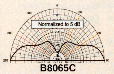
Gain factor is the way the radiation pattern lays down on the horizon - with more power - lower to the horizon - the transceiver has a more effective gain to the cellular RF system.
Yagi
For a very remote installation, a directional antenna (may be desired. This
type of antenna concentrates the transmitted power in the direction it is
pointed. These antennas can be designed to have a wide “beam-width” or a narrow
“beam-width”. The narrower the “beam-width”, the higher the gain of the
antenna.
It is
critical that directional antennas be pointed directly at the cell site. The
direction of the nearest cell site can be determined by contacting the cellular
carrier for your area.
6.2
Antenna Installation Guidelines
·
the distance to
the nearest cell site
·
the degree of
down-tilt used on the cell site antenna array
·
the type of
terrain and foliage between the antenna and cell site
·
the existence of
man-made obstacles such as buildings and/or water towers between the antenna and
cell site or radio interference.
·
the distance
between the Cell modem antenna placement
·
the height of
the antenna above ground level
· the type and length of cable used to attach the antenna to the Cell modem
6.2.1
Know the location(s) of the closest cell site(s). The cellular carrier can
provide the appropriate location information. This information will assist you
in positioning antennas and enable you to do a path check between the cell site
and your location for any man-made or natural obstacles.
6.2.2
Man-made and natural obstacles
such as buildings, water towers, mountains, hills and trees can cause the
cellular signal to deteriorate or even block the signal. Raising the antenna,
relocating the antenna, or choosing a higher gain antenna may improve reception.
6.2.4
The type and
placement needs of the antenna can vary significantly over a small distance (as
little as a few feet horizontally and/or vertically), so different antenna
placement locations should be tried if a high quality connection between the
cellular system and the Cell modem is not established or ahs a high error rate.
6.2.5
Always elevate the antenna as
high as possible so that it has a clear path to the cell site.
6.2.6
If the installation location
is well within the range of the cell site, a unity gain antenna or a 3dB gain
antenna should be sufficient for an acceptable signal strength. However, if the
installation is on the “fringe” or just outside the range of the cell site, a
higher gain, directional antenna may be needed to establish an acceptable
connection.
6.2.7
The antenna cable should be
laid as straight as possible with no kinks, twists or bends. If the cable has be
to coiled, keep the radius of the coils as large as possible.
6.2.8
The antenna and cable should
be as far away from any other transmission sources as possible to minimize
potential interference from those sources. Other transmission sources include
other antennas, radio frequency (RF) generators and AC power lines.
6.2.9
If attempts to establish a
high quality connection are unsuccessful, relocation of the entire installation
may be necessary. Prior to moving the entire installation, attempt to access a
different cell site through the use of directional high gain antenna. Even
though the cell site may be farther away, the different direction may avoid
man-made or natural obstacles that are blocking the cellular signal.
6.2.10
Remember that while the distance that the Cell modem unit can be from the
antenna is limited, the distance from the CS-832 to the meter/telephone
equipment to which it is connected can be 1000 feet or more. Thus, the Cell
modem does not have to be located with the meter/telephone equipment to
function properly. This aspect of the equipment gives significant additional
flexibility in the installation process.
6.2.11
No matter what type of antenna
is being used, propagation patterns vary, as does reception. You may want to
try different locations to achieve the best results, even if a given location
appears adequate. Once the best antenna type and location is determined,
permanently mount the antenna.
Elevated Feed
Omni
antennas are designed for most cellular installations. These antennas can be
mounted under a variety of scenarios and will provide adequate signal strength
for data applications in most areas. You should use an antenna that does not
require a ground plane and should be mounted as high as possible with a direct
line of sight to the nearest cellular site with the shortest coax lead possible.
Mount the antenna VERTICALLY
on a solid surface in a location so that its perimeter is clear of any metal
objects and/or obstacles.
Yagi
Point the antenna towards the
cell site. Make sure the elements (the bars on the antenna) are positioned
vertically. It should be in a location so that the transmission path is clear
of any nearby metal objects and/or obstacles.
jump to Mobil antennas
ARC ELECTRONICS
301-924-7400 EXT 25 / 301-924-7400 EXT 25 / fax 301-924-7403
jump to ... Home Page
arc@arcelect.com