Link1 TADILB Modem - FSK Analog Modem, V.23, Sync or Async
|
PC ISA Card Format |
- Full duplex rates to 1200 bps (in async V.23 mode)
- Asynchronous or synchronous RS-232
- 4-wire, full duplex line application
- Standalone or rack mount
- PC card rack mode (PC supplies power and ground only)
- High stability transmit and receive frequency
- Ruggedized for full temperature range application
The Link1 TADILB modem operates at 600 and 1200 bps, synchronous or
asynchronous, with V.23 modulation. The modem accepts external transmit clock on
pin 24. The modem operates in Link1 DFSK mode (differential frequency shift key)
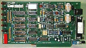
at 600 and 1200 bps. Full 13.5” PC card, 7.25” half card size, and
standalone configurations are available. The pc card uses the internal pc ISA
bus only for power from the pc bus. The serial terminal interface is RS-232,
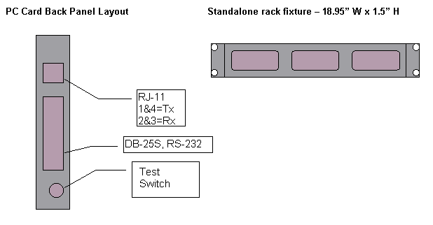
DB-25. The phone line connector is an RJ-11 for 4-wire leased line operation.
Transmit is on positions 2 and 3, receive 1 and 4 of the 4 position RJ-11
connector.
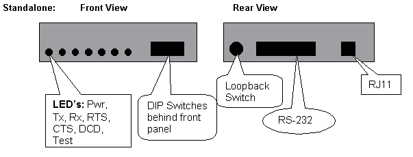
The modem has DIP switch controls for the TADIL-B (V.23) or LINK1 mode, for
1200 or 600 bps operation, for 4 or 8 ms RTS/CTS delay, for constant carrier
(RTS forced on) or terminal controlled RTS, and transmit level settings of +3,
0, -16 and –30 dBm. The modem has a push/push switch for local digital loop on
or off. The DIP switch is located on the PC card and is accessible behind the
front panel of the standalone modem. The loopback switch is located on the rear
of the unit, next to the DB-25 terminal connector.
- Analog full duplex
- 4-wire, 600 ohm balanced
- Frequency Shift Keying with the following logic:
- Mark 1300 hertz at 600 and 1200 bps
- Space 1700 hertz at 600 bps
- 2100 hertz at 1200 bps
- DFSK. Differential Frequency Shift Keyed (Link1 mode)
- 600 and 1200 bps
- Transmit and Receive clock supplied by modem
- Modem supplies transmit clock and recovered received clock, allowing the
modem to run sync or async without a switch
- Transmit level control from +3 dBm to -30 dBm, implement as +3, 0 –16
and –30
- The modem operates with no errors when signal interruptions occur at less
than 1/4 of a bit length (300 microseconds) at the selected bit rate
- The modem operates with no errors when the signal level changes up to 25
dBm
- The modem will drive up to 100 meters of cable (approximately 30 Km cable,
depending upon wire gauge)
- Switched carrier or constant carrier operation (RTS forced on or terminal
controlled)
- RS-232, DB-25S
- Signals are Tx, Rx, RTS, CTS, DSR, DCD, TxClock, RxClock, Ext TxClock
- RTS/CTS delay is 4 or 8 ms in switched carrier mode. In constant carrier
mode RTS/CTS is forced on
- Rx data is clamped to mark when no receive carrier detect is present. Rx
clock continues to run when carrier detect is off
- Power, Tx Data, Rx Data, RTS, CTS, DCD, Test
- Power turns on when the modem is powered
- TxData and RxData LED's light for RS232 SPACE condition
- RTS, CTS and DCD LED's light for RS232 HIGH condition
- Digital loop via rear panel switch. Test LED lights during test. Loopback
on when switch is pushed in, Loopback is off when switch is out
- Switch for mode, speeds, RTS control, RTS/CTS delay, clocking, transmit
levels
- Controlled carrier (with RTS/CTS delay) or constant carrier
with RTS/CTS on
- RTS/CTS delay of 4 or 8 ms
- Analog Loop or normal operation
- Internal timing or external transmits timing
- Synchronous speeds of 600 or 1200 bps
- Transmit level of +3 db, 0 db, -16db or -30db
- L1 (DFSK Mode) or TADILB (V.23 mode)
OPTION SWITCH SETTINGS
| Switch |
DOWN |
UP |
| 1 – mode |
TADIL-B mode (V.23) |
LINK1 mode |
| 2 – Speed |
1200 bps |
600 bps |
| 3 - RTS/CTS delay |
4 ms |
8 ms |
| 4 – Carrier |
Constant |
RTS controlled |
| 5 – Clocking |
Internal TxClock |
External (pin 24) |
| 6 - Tx Level |
see table |
|
| 7 - Tx Level |
see table |
|
| 8 - Loopback |
Loopback ON |
Loopback OFF |
Transmit Audio Level Settings:
| Level |
Switch 6 |
Switch 7 |
| +3 dBm |
UP |
UP |
| 0 |
UP |
DOWN |
| -16 (-8 on rev A) |
DOWN |
UP |
| -30 (-16 on rev A) |
DOWN |
DOWN |
- -35C to +70C operating temperature range
- PC ISA bus format or standalone version
- PC bus is used for power and ground only, standalone unit uses 110V wall
mount supply
- Half size PC card, 7”D x 4.25”H
- Stand alone: 5.5” W x 7.375”D x 1.5” high, 110VAC wall mount supply
- A 1.5” x 19” fixture is available for rack mounting up to 3 standalone
units in a single 1U height
- 20 slot rack chassis is 16.5”W x 16”D x 7”H, 110VAC 250 W power
supply
- Wall-mount power supply 120VAC
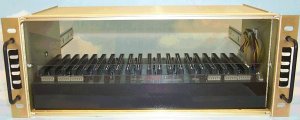
PC Card Rack Chassis
The Link1 TADILB modem is normally used with standards based equipment that
requires reliability rather than speed. The PC ISA format card is used in a
standard PC ISA chassis. It draws power from that chassis and has no other
internal chassis connections. There is a 20 slot ISA chassis available for this
format with built-in power supply. The stand-alone model uses a wall-mount AC
power supply. There is a 3 unit rack mount available for the stand-alone model.
Related pages
ARC ELECTRONICS
301-924-7400 EXT 25
jump to ... Home Page
arc@arcelect.com