|
ARC 2.4bps Industrial Modem |
HARDENED INDUSTRIAL GRADE MODEMS
Bell 103, 212, V.22, V.22bis, DC Power & 115 VAC -
Double Surge Protection - Temp Rated
To service the growing
need for efficient, reliable data communications in the harsh environments of
"remote" remote sites and industrial facilities. ARC has developed a
family of data communications products that can operate from various AC &
DC power supplies and survive high surge levels and extreme heat and cold.
ARC modems work
in "remote" remote sites with very low failure rates. These devices
work where other modems roll over and die. When a service call to a remote
site can mean an all day trip these modems are the ideal solution.
Requires very little power making them ideal for solar powered
applications
|
|
|
|
SPECIFICATIONS
|
IM 24 |
|
Max. Data throughput |
2,400 bps |
|
Asynchronous 10 bit codes |
Yes |
|
Data Speed |
2,400 bps |
|
Hardware MNP 5 & V.42 bis |
No |
|
Auto Baud |
Yes |
|
" AT " commands |
Yes |
|
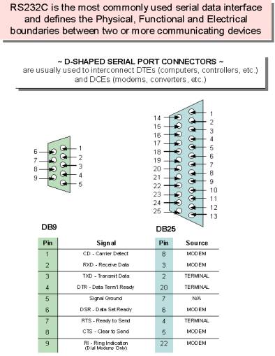
RS 232 Interface, Female DB9 |
Yes |
|
Led
Indicators |
Yes |
|
Regulatory Approvals |
FCC |
|
10 to 36VDC or 18 to 72VDC |
Yes |
|
Max. Current Consumption |
50 ma @48VDC |
|
Normal Current Consumption |
25 ma @48VDC |
|
Power Input Low VDC |
10-36 VDC |
|
Max. Current Consumption |
100 ma @12VDC |
|
Normal Current Consumption |
60 ma @12VDC |
|
10-36
VDC Model Part # IM24LV |
IM24LV |
|
Double Surge Protection |
Yes |
|
Temp. Rating -30 to 70 C |
Yes |
|
115VAC power cube option |
Yes |
|
Environmental: 95% humidity, noncondensing - Optional Coatings for high humidity |
Yes |
|
Size 3.5" W, 6" L, 1" H |
3.5" W, 6" L, 1" H |
Modem Module
The base unit houses the power and Data & Telecom
interfaces and uses Modem Modules that can be upgraded from 2.4 to14.4 to
33.6Kbps. This allows upgrades by replacing just the Modem Module.
|
Modem Module 2400 bps |
|
|
FEATURES:
|
|
Max. Data throughput |
2400 bps |
|
Data Speed |
2400 bps |
|
Hardware MNP 5 & V 42 bis |
- |
|
Auto Baud |
Yes |
|
" AT " Commands |
Yes |
|
Regulatory Approvals |
FCC 68-15 |
|
Software compatibility with all existing data software |
Yes |
|
Custom Configurations |
Yes |
SUMMARY
OF THE ROCKWELL "AT" COMMAND SET
To communicate using the
modem, use an asynchronous communication program. The command set for the
modems is compatible with the Hayes command set.
The modem is
controlled and configured by the AT (attention command). Each command consists
of the following elements (with the exception of the A/and the +++ command
that will be discussed later). A command is not entered until a carriage
return <ENTER> is entered. Spaces entered are ignored. For example, to
enter the command `Answer', type ATA and <ENTER>.
Some commands do not have
parameters. Any missing parameters in a command is assigned the value zero,
which may be a valid parameter for the command. The sequence followed by AT
command causes the modem to enter a command state. That is, AT without a
command serves as a wake up code and an "OK" appears on the screen.
The modem queues the commands in a 40-character command line. The
command line begins with AT and can have several commands. A separator is not
required between the commands.
When a carriage
return is received, the commands are performed in the order in which they are
sent to the modem. If more than 40 characters are sent to the modem, an error
occurs and all commands must be re-entered.
A
common configuration for a remote modem is to answer the call and hang up on
loss of carrier. To do this the RS232 interface has to be set for the correct
configuration.
Option
if the Computer uses pins 2, 3, & 7 only - Set the AT commands as follows
ATS0=1
(modem will answer on the first ring)
AT&D0 (modem will ignore DTR)
factory default is AT&D1 which allows the modem to answer only if DTR is
high.
AT&V to check the state of the "S" registers use AT&V
AT&W0 Don't forget to burn the new codes into E-PROM by AT&W0 or W1
To see your typing you
made need to turn on E1 for the modem to echo back responses. Some software
doe not like it's data echoed back so don't forget to check E1/E0 if your
software is acting strange.
Note: you may want to put the modem into a quiet mode - ATQ1
(ATQ0 is the default) modem does not send result codes - which can confuse the
computer.
A
good configuration for a dumb mode operation is
BASIC AT COMMANDS for the 2,400 modem
Command and Data Modes
When you first start up your communications software, you will be in COMMAND mode. In other words, you have not dialed out and linked up to a remote modem. In COMMAND mode, local commands (called AT Commands) are active. After dialing out and successfully linking-up, you are in DATA mode and AT Commands are no longer active. In DATA mode, you must use the ESCAPE code ( . ) to temporarily suspend transmission to the remote modem and re-enter COMMAND mode. The ATO<CR> command (see below) reenters DATA mode.
AT Command Summary
All of the following commands must be preceded with the characters AT and followed by a carriage return (the <CR>, < <enter> >, or < <return> > key). For example, typing AT<CR> will cause the modem to print "OK" on the screen, and typing
AT&V<CR> will print the current configuration profile on the screen. The one notable exception is the A/ command, which will execute the previous AT Command without a <CR>. Throughout the rest of the manual, we will use the <CR> symbol to represent the enter key.
Be sure to do a AT&W0 that will write the changes you may have made to the 0 register so the modem will not lose it's settings after a power outage
You may want to set the modem up so it will echo your key strokes with the E1 command -
NOTE some software will have problems with an echo so you may need to set it to E1.
If your RS232 interface doesn't supply DTR you will need to set the &D to
Basic Commands
- AT-Command prefix required before all
- commands except A/ and ESCAPE sequences
- <CR>-Terminates command line
- A/-Repeat last command (does not use
- <CR>)
- + + + Escape code sequence
(returns to
COMMAND mode from DATA mode) - A-Answers a telephone call
- Bn-Select Bell or CCITT for 1200 bps
- connection
- B0-CCITT V.22 FOR 1200 bps
- communication
- Bl-Bell 212A for 1200 bps communication
- Cn-Carrier Control
- C0-ERROR
- C1-OK
- D-Dial the number which follows (see DIAL commands)
- En-Command set echo control
- E0-Echo off
- E1-Echo on
- Fn-On-line echo
- F0-ERROR
- Fl-OK
- Hn-Off-hook control
- H0-Hangup phone line
- H1-Pickup phone line
- In-Identify the modem type
- I0-Report the product code
- I1-Calculate the firmware ROM checksum
- I2-Verify the firmware ROM checksum
- I3-Report the firmware and revision levels
- I4-Report modem capabilities and features
- Ln-Speaker volume control Acknowledged
- Mn-Speaker control Acknowledged
- O-Go back to DATA mode
- P-Use pulse dialing
- Qn-Disables (quiets) command responses
- Q0-Enable results
- Q1-Disable results
- Sn-Select a S register
- Sn=-Set S register to new value
- Sn?-Show value of S register
- T-Use tone dialing
- Vn-Use verbose result codes
- V0-Result codes are numeric
- V1-Result codes are verbose
- Xn-Extended dialing result codes
- X0-Send result codes 0 through
4; BUSY
and DIAL TONE detect disabled - X1-Send result codes 0 through
5, 10;
BUSY and DIAL TONE detect disabled - X2-Result codes 0 through 6,
10 enabled;
BUSY detect disabled, DIAL TONE detect enabled - X3-Result codes 0 through 5, 7, 10 enabled;
- BUSY detect enabled, DIAL TONE detect disabled
- X4-Result codes 0 through 8, 10 enabled;
- BUSY and DIAL TONE detect enabled
- Yn-Enable long space disconnect
- Y0-Disable long space disconnect
- Y1-Enable long space disconnect
- Zn-Reset the modem
- Z0-Reset and use stored profile 0
- Z1-Reset and use stored profile 1
- , -Pause for the value (in seconds) stored in register S8
Dial Commands
- DP-Pulse dial the telephone number
- DS=n-Dial with previously stored number
- DT-Tone dial the telephone number
- DW-Wait for dial tone
- D; - Stop dialing and wait for more commands
- D@ - Wait for 5 seconds of silence
- D! - Hang up for 1/2 of a second (Flash)
- D,-Pause for seconds as determined by register S8
- 0 through 9, A, B, C,
D, #, *- Dial Digits/Characters
When the modem is dialing a phone number, any key will abort the current dialing command.
Extended Commands
- &Cn-EIA RS-232 DCD control
- &C0-Always on
- &C1-On only when carrier detected
- &Dn-EIA RS-232 DTR control Acknowledged
- &En-Dialing echo control
- &E0-Disable dialing echo
- &E1-Enable dialing echo
- &F-Accept factory settings
- &Gn-Guard tone control
- &G0-Guard tones disabled
- &Gl-Guard tone disabled
- &G2-1800-Hz Guard tone enabled
- &Ln-Leased-line control Acknowledged
- &Pn-Select pulse dial make/break ratio
- &P1-39 through 61 make/break at 10 pps
- &P2-33 through 67 make/break at 10 pps
- &Sn-EIA RS-232 DSR control Acknowledged
- &V-VIEW current configuration profile
- &Wn-Write to stored profile
- &W0-Write settings to stored profile 0
- &W1-Write settings to stored profile I
- &Yn-Select stored profile for power up
- &Y0-Use profile 0 on power up
- &Y1-Use profile I on power up
- &Zn=val-Store dial string (up to 36 characters) in nonvolatile memory location numbers 0 through 3
Register Commands
* means value is stored by &Wn (0 or1) command.
• S0*-Number rings until auto answer S0=1 will answer one the first ring
• S1-Number of rings received
• S2-Escape Character
• S3-Carriage-return character
• S4-Line-feed character
• S5-Backspace character
• S6-Time for dial tone
• S7-Time to wait for connection
• S8-Pause time for comma
• S9-Carrier detect time
• S10-Carrier lost detect time
• S11-Tone dialing speed
• S12-Escape-code guard time
• S14*-bit-mapped options register
• S21*-bit-mapped options register
• S22*-bit-mapped options register
• S23*-bit-mapped options register
• S27*-bit-mapped options register
Result Code Summary
* OK-Command was executed without error
* 1 CONNECT-Modem has detected carrier and has gone DATA
* 2 RING-Modem has detected ringing
* 3 NO CARRIER-Carrier has been lost and call has been hung up
* 4 ERROR-Error in command line
* 5 CONNECT 1200-Modem has connected at 1200 bps; Bell 212 or V.22 connection
* 6 NO DIAILTONE-has been detected
* 7 BUSY-A busy signal has been detected
* 8 NO ANSWER-Silence was not found
* 10 CONNECT 2400-Modem has connected at 2400 bps; V-22 connection
Error Diagnostics
Is the computer talking with the modem?
When you type AT<CR>, "OK" should be displayed. If the modem does not respond:
1. Make sure the modem is firmly connected to the computer.
2. Verify the communication program is configured to the correct communications port (COM L, COM2:, COM3:, or COM4:).
3. Verify the baud rate (2400, 1200, or 300) and check parity (even, odd, none).
4. If the modem still does not respond, type AT&F<CR>. This will reset the modem to the original factory settings.
5. Try unplugging the modem and plugging it back in to ensure clean contact connections.
If the modem responds, but...
---characters are not displayed, type ATEI <CR>. This tells the modem to echo commands to the screen.
...characters are displayed double, type
ATE<CR>. This turns the echo feature off.
Modem does not answer.
If the modem does not answer an incoming call, type
ATSO = I < CR>.
Modem will not dial a telephone number.
If the computer displays NO DIALTONE, the modem is not receiving a dial tone. Connect a standard telephone to the telephone line to verify a dial tone. If you do not hear dial tone, something is wrong with either your telephone cable or telephone line. Try another cable or line.
On some telephone lines connected to internal telephone systems, the telephone lines are not standard and will not work with standard telephones. Such lines will not work with this modem. Adapters are available to convert these lines so they may work with standard telephone equipment.
Modem can dial but can't communicate.
If you cannot communicate properly, something may be wrong with the other system. Try calling a different modem.
Unusual characters appear on the screen.
If you can dial, but unusual characters appear on the screen while communicating, check the communications settings of your communications software. The most common settings are 7EI (7 bits, even parity, I stop bit) and 8N 1 (8 bits, no parity, I stop bit).
Modem connects but cannot communicate.
Another possibility is that your modem and software are set for different speeds. In other words, you will be unable to communicate at 2400 bps with modems linked at 1200 bps. Check your speed settings.
Your modem disconnects.
During communications the modem may disconnect from the phone line if-
1. It fails to connect to the remote modem.
2. It detects a loss of carrier from the remote modem.
3. You enter the escape and Hook command.
4. Turn off power to the computer.
|
LED's
·
TR = DTR, Data Terminal Ready
·
TX = Transmit Data
·
CD = Carrier Detect from remote modem
·
RX = Receive Data
·
PWR = Power |
|
Power connection
·
Positive is on the left power terminal
·
Negative is on the right terminal
·
Power will be 10 to 36 VDC for LV and · 110VAC use DC Wall power cube |