|
ARC Industrial Modem
IM-144
& IM-336
|
Industrial Grade Modems
300 - 1,200 - 2,400 - 4,800 - 7,200 - 9,600 - 14,400 - 33,600BPS
low voltage 10 to 36VDC - high voltage 18 to 72VDC / 110/220VAC 60/50 cycle AC
HARDENED INDUSTRIAL GRADE MODEMS
Bell 103, 212, V.22, V.22bis, V.32, V.32bis, V.34
9 to 72 Volt DC Power & 115 VAC - Double Surge Protection - Temp Rated
To service the growing need
for efficient, reliable data communications in the harsh environments of
"remote" remote sites and industrial facilities. ARC has developed a
family of data communications products that can operate from various AC &
DC power supplies and survive high surge levels and extreme heat and cold.
Requires very little power making them ideal for solar powered
applications
|
|
- .3, 1.2, 2.4, 9.6, 4.8, 7.2, 14.4, & 33.6kbps
- 10VDC
to
72 VDC Power & 115VAC
- Double Surge Protection
- -20oC
to +70oC Operating Temp.
- LEDs - TX, RX, CD, DTR,
PWR
- Ideal for Solar Powered Applications
- Mounting Tabs
- DIN Rail Mounting
|
The base unit uses Modem Modules that can be interchanged.
SPECIFICATIONS
|
SPECIFICATIONS
|
IM
144
|
IM
336
|
|
Max. Data throughput
|
57,600 bps
|
134,400 bps
|
|
Data Speed
|
300/1,200/2,400/
4,800/7,200/9,600
14,400 bps
|
300/1,200/2,400/
4,800/7,200/9,600
14,400 bps/33,600 bps
|
|
Hardware MNP 5 & V 42 bis
|
Yes
|
Yes
|
|
Auto Baud
|
Yes
|
Yes
|
|
" AT " commands
|
Yes
|
Yes
|
|
RS 232 Interface
|
Yes
|
Yes
|
|
Led Indicators TX, RX, CD,
DTR, PWR
|
Yes
|
Yes
|
|
Regulatory Approvals
|
FCC
|
FCC
|
|
Power Input
|
18-72 V DC
|
18-72 V DC
|
|
Max. Current Consumption
|
70 ma @48VDC
|
70 ma @48VDC
|
|
Normal Current Consumption
|
35 ma @48VDC
|
35 ma @48VDC
|
|
Power Input Option 7-12VDC
|
12 VDC
|
12 VDC
|
|
Max. Current Consumption
|
140 ma @12VDC
|
140 ma @12VDC
|
|
Normal Current Consumption
|
100 ma @12VDC
|
100 ma @12VDC
|
|
7-12 VDC Operation Model Part #
18-72 VDC Operation Model Part #
|
IM 144-12
IM-024-48
|
IM 336-12
IM-024-48
|
|
Heat Rating -20 to 70 C
|
Yes
|
Yes
|
|
115VAC power cube
|
Yes
|
Yes
|
|
Environmental: 95% humidity, noncondensing
- Optional Coatings for high humidity
|
Yes
|
Yes
|
|
Size 3.5" W, 6" L, 1" H
|
Yes
|
Yes
|
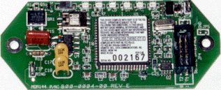
Modem Modules
The base unit houses the power and Data & Telecom
interfaces and uses Modem Modules that can be upgraded from 2.4 to14.4 to
33.6Kbps. This allows upgrades by replacing just the Modem Module.
|
Modem Module 14,400 bps & 33,600 bps
|
|
|
FEATURES:
- Complete 14400 or 33.6 Kbps modem modules
- FCC approved
|
|
MM144
|
300/1,200/2,400/
4,800/7,200/9,600
14,400 bps
|
|
MM336
|
300/1,200/2,400/
4,800/7,200/9,600
14,400 33,600 bps
|
|
Max. Data throughput
MM144
|
14,400 bps
57,600 bps
|
|
Max. Data throughput
MM336
|
33,600 bps
115,000 bps
|
|
Hardware MNP 5 & V.42 bis
|
Yes
|
|
Auto Baud
|
Yes
|
|
" AT " Commands
|
Yes
|
|
Regulatory Approvals
|
FCC
|
|
Software compatibility with all existing
data software
|
Yes
|
|
Custom Configurations
|
Yes
|
SUMMARY
OF THE ROCKWELL "AT" COMMAND SET
To communicate using the
modem, use an asynchronous communication program. The command set for the
modems is compatible with the Hayes command set.
The modem is
controlled and configured by the AT (attention command). Each command consists
of the following elements (with the exception of the A/and the +++ command that
will be discussed later). A command is not entered until a carriage return
<ENTER> is entered. Spaces entered are ignored. For example, to enter the
command `Answer', type ATA and <ENTER>.
Some commands do not have
parameters. Any missing parameters in a command is assigned the value zero,
which may be a valid parameter for the command. The sequence followed by AT
command causes the modem to enter a command state. That is, AT without a
command serves as a wake up code and an "OK" appears on the screen.
The modem queues the commands in a 40-character command line. The command
line begins with AT and can have several commands. A separator is not required
between the commands.
When a carriage
return is received, the commands are performed in the order in which they are
sent to the modem. If more than 40 characters are sent to the modem, an error
occurs and all commands must be re-entered.
A
common configuration for a remote modem is to answer the call and hang up on
loss of carrier. To do this the RS232 interface has to be set for the correct
configuration.
Option
if the Computer uses pins 2, 3, & 7 only - Set the AT commands as follows
ATS0=1 (modem will answer on the
first ring)
AT&D0 (modem will ignore DTR) factory default is
AT&D1 which allows the modem to answer only if DTR is high.
AT&V to check the state of the "S"
registers use AT&V
AT&W0 Don't forget to burn the new codes into
E-PROM by AT&W0
To see your typing you made
need to turn on E1 for the modem to echo back responses. Some software doe not
like it's data echoed back so don't forget to check E1/E0 if your software is
acting strange.
Note: you may want to put
the modem into a quiet mode - ATQ1 (ATQ0 is the default) modem does not send
result codes -
which can confuse the computer.
A good
configuration for a dumb mode operation is AT&F&C1&D0E0Q1S0=1&W0
BASIC AT COMMANDS for the 14.4 & 33.6
MODEM MODULE...
Command Function
A/ Re-execute command.
A Go off-hook and attempt to answer a call.
B0 Select V.22 connection at 1200 bps.
B1 Select Bell 212A connection at 1200 bps.
C1 Return OK message.
Dn Dial modifier.
E0 Turn off command echo.
E1 Turn on command echo.
F0 Select auto-detect mode (equivalent to N1).
F1 Select V.21 or Bell 103.
F2 Reserved.
F3 Select V.23 line modulation.
F4 Select V.22 or Bell 212A 1200 bps line speed.
F5 Select V.22 bis line modulation.
F6 Select V.32 bis or V.32 4800 line modulation.
F7 Select V.32 bis 7200 line modulation.
F8 Select V.32 bis or V.32 9600 line modulation.
F9 Select V.32 bis 12000 line modulation.
F10 Select V.32 bis 14400 line modulation.
H0 Initiate a hang-up sequence.
H1 If on-hook, go off-hook and enter command mode.
I0 Report product code.
I1 Report pre-computed checksum.
I2 Report OK.
I3 Report firmware revision, model, and interface type.
I4 Report response "Telenetics Inc. Rev"
I5 Report the country code parameter.
I6 Report modem data pump model and code revision.
I7 Reports the DAA code
L0 Set low speaker volume.
L1 Set low speaker volume.
L2 Set medium speaker volume.
L3 Set high speaker volume.
M0 Turn speaker off.
M1 Turn speaker on during handshaking and turn speaker off while
receiving carrier.
M2 Turn speaker on during handshaking and while receiving
carrier.
M3 Turn speaker off during dialing and receiving carrier and
turn speaker on during answering.
N0 Turn off automode detection.
N1 Turn on automode detection.
O0 Go on-line.
O1 Go on-line and initiate a retrain sequence.
P Force pulse dialing.
Q0 Allow result codes to DTE.
Q1 Inhibit result codes to DTE.
Sn Select S-Register as default.
Sn? Return the value of S-Register n.
=v Set default S-Register to value v.
? Return the value of default S-Register.
T Force DTMF dialing.
V0 Report short form (terse) result codes.
V1 Report long form (verbose) result codes.
W0 Report DTE speed in EC mode.
W1 Report line speed, EC protocol and DTE speed.
W2 Report DCE speed in EC mode.
X0 Report basic call progress result codes, i.e., OK, CONNECT,
RING, NO CARRIER (also, for busy, if enabled, and dial tone not detected),NO
ANSWER and ERROR.
X1 Report basic call progress result codes and connections
speeds (OK, CONNECT, RING, NO CARRIER (also, for busy, if enabled, and dial
tone not detected), NO ANSWER, CONNECT XXXX, and ERROR.
X2 Report basic call progress result codes and connections
speeds, i.e., OK, CONNECT, RING, NO CARRIER (also, for busy, if enabled, and
dial tone not detected), NO ANSWER, CONNECT XXXX, and ERROR.
X3 Report basic call progress result codes and connection rate,
i.e., OK, CONNECT, RING, NO CARRIER, NO ANSWER, CONNECT XXXX, BUSY, and ERROR.
X4 Report all call progress result codes and connection rate,
i.e., OK, CONNECT, RING, NO CARRIER, NO ANSWER, CONNECT XXXX, BUSY, NO DIAL
TONE and ERROR.
Y0 Disable long space disconnect before on-hook.
Y1 Enable long space disconnect before on-hook.
Z0 Restore stored profile 0 after warm reset.
Z1 Restore stored profile 1 after warm reset.
&C0 Force RLSD active regardless of the
carrier state.
&C1 Allow RLSD to follow the carrier state.
&D0 Interpret DTR ON-to-OFF transition per
&Qn:
&Q0, &Q5, &Q6
The modem ignores DTR.
&Q1, &Q4 The modem hangs up.
&Q2, &Q3 The modem hangs up.
&D1 Interpret DTR ON-to-OFF transition per
&Qn:
&Q0, &Q1, &Q4,.
&Q5, &Q6 Asynchronous escape.
&Q2, &Q3 The modem hangs up.
&D2 Interpret DTR ON-to-OFF transition per
&Qn:
&Q0 through &Q6 The
modem hangs up.
&D3 Interpret DTR ON-to-OFF transition per
&Qn:.
&Q0, &Q1, &Q4,.
&Q5, &Q6 The modem
performs soft reset.
&Q2, &Q The modem
hangs up.
&F0 Restore factory configuration 0.
&F1 Restore factory configuration 1.
&G0 Disable guard tone.
&G1 Disable guard tone.
&G2 Enable 1800 Hz guard tone.
&J0 Set S-Register response only for
compatibility.
&J1 Set S-Register response only for
compatibility.
&K0 Disable DTE/DCE flow control.
&K3 Enable RTS/CTS DTE/DCE (Hardware) flow
control.
&K4 Enable XON/XOFF DTE/DCE (Software) flow
control.
&K5 Enable transparent XON/XOFF flow control.
&K6 Enable both RTS/CTS and XON/XOFF flow
control.
&L0 Select dial up line operation.
&L1 Select leased line operation.
&M0 Select direct asynchronous mode.
&M1 Select sync connect with async off-line
command mode. *
&M2 Select sync connect with async off-line
command mode and enable DTR dialing of directory zero. *
&M3 Select sync connect with async off-line
command mode and enable DTR to act as Talk/Data switch. *
&P0 Set 10 pps pulse dial with 39%/61%
make/break.
&P1 Set 10 pps pulse dial with 33%/67%
make/break.
&P2 Set 20 pps pulse dial with 39%/61%
make/break.
&P3 Set 20 pps pulse dial with 33%/67%
make/break.
&Q0 Select direct asynchronous mode.
&Q1 Select sync connect with Async off-line
command mode. *
&Q2 Select sync connect with Async off-line
command mode and enable DTR dialing of directory zero. *
&Q3 Select sync connect with Async off-line
command mode and enable DTR to act as Talk/Data switch. *
&Q4 Select Hayes AutoSync mode.
&Q5 Modem negotiates an error-corrected link.
&Q6 Select asynchronous operation in normal
mode.
&R0 CTS tracks RTS (Async) or acts per V.25
(sync).
&R1 CTS is always active.
&S0 DSR is always active.
&S1 DSR acts per V.25.
&T0 Terminate any test in progress.
&T1 Initiate local analog loopback.
&T2 Returns ERROR result code.
&T3 Initiate local digital loopback.
&T4 Allow remote digital loopback.
&T5 Disallow remote digital loopback request.
&T6 Request an RDL without self-test.
&T7 Request an RDL with self-test.
&T8 Initiate local analog loop with self-test.
&V Display current configurations.
&W0 Store the active profile in NVRAM profile
0.
&W1 Store the active profile in NVRAM profile
1.
&X0 Select internal timing for the transmit
clock.
&X1 Select external timing for the transmit
clock.
&X2 Select slave receive timing for the
transmit clock.
&Y0 Recall stored profile 0 upon power up.
&Y1 Recall stored profile 1 upon power up.
&Zn=x Store dial string x (to 35) to location n (0
to 3 depending upon modem model).
%E0 Disable line quality monitor and auto retrain.
%E1 Enable line quality monitor and auto retrain.
%E2 Enable line quality monitor and fallback/fall forward.
%L Return received line signal level.
%Q Report the line signal quality.
\D1 Enable Auto Dial via DTR off to on sequence *PE14400 only
\D0 Disable Auto Dial (default) *PE14400 only
\G0 Disable modem to modem flow control.
\G1 Enable modem to modem flow control.
\H0 Command Mode default
\H1 Lease Line Mode
\Kn Controls break handling during three states:
When modem receives a break from the DTE:
\K0,2,4 Enter on-line command mode, no break sent to
the remote modem.
\K1 Clear buffers and send break to remote modem.
\K3 Send break to remote modem immediately.
\K5 Send break to remote modem in sequence with transmitted data.
When modem receives \B in on-line command state:
\K0,1 Clear buffers and send break to remote
modem.
\K2,3 Send break to remote modem immediately.
\K4,5 Send break to remote modem in sequence with
transmitted data.
When modem receives break from the remote modem:
\K0,1 Clear data buffers and send break to DTE.
\K2,3 Send a break immediately to DTE.
\K4,5 Send a break with received data to the DTE.
\M0 Select Answer Mode (Lease Line) with \H1 active
\M1 Select Originate Mode (Lease Line) with \H1 active
\N0 Select normal speed buffered mode.
\N1 Select direct mode.
\N2 Select reliable link mode.
\N3 Select auto reliable mode.
\N4 Force LAPM mode.
\N5 Force MNP mode.
\S0 Unlock command mode (normal mode) *PE14400 only
\S1 Lock (out) command mode (security mode) *PE14400 only
Error
Diagnostics
Is the computer talking with the modem?
When you type AT<CR>, "OK" should be displayed.
If the modem does not respond:
1. Make sure the modem is firmly connected to the computer.
2. Verify the communication program is configured to the correct com port (COM
L, COM2:, COM3:, or COM4:).
3. Verify the baud rate (2400, 1200, or 300) and check parity (even, odd,
none).
4. If the modem still does not respond, type AT&F<CR>. This will
reset the modem to the original factory settings.
5. Try unplugging the modem and plugging it back in to ensure clean contact
connections.
If the modem responds, but...
---characters are not displayed, type ATEI <CR>. This tells the modem
to echo commands to the screen.
...characters are displayed double, type ATE<CR>. This turns the echo
feature off.
Modem does not answer.
If the modem does not answer an incoming call, type
ATSO = I < CR>.
* Check to make sure your terminal device has DTR high
Modem will not dial a telephone number.
If the computer displays NO DIALTONE, the modem is not receiving a
dial tone. Connect a standard telephone to the telephone line to verify a dial
tone. If you do not hear dial tone, something is wrong with either your
telephone cable or telephone line. Try another cable or line.
On some telephone lines connected to internal telephone systems, the
telephone lines are not standard and will not work with standard telephones.
Such lines will not work with this modem. Adapters are available to convert
these lines so they may work with standard telephone equipment.
Modem can dial but can't communicate.
If you cannot communicate properly, something may be wrong with the other
system. Try calling a different modem.
Unusual characters appear on the screen.
If you can dial, but unusual characters appear on the screen while
communicating, check the communications settings of your communications
software. The most common settings are 7EI (7 bits, even parity, I stop bit)
and 8N 1 (8 bits, no parity, I stop bit).
Modem connects but cannot communicate.
Another possibility is that your modem and software are set for different
speeds. In other words, you will be unable to communicate at 2400 bps with
modems linked at 1200 bps. Check your speed settings.
Your modem disconnects.
During communications the modem may disconnect from the phone line if-
1. It fails to connect to the remote modem.
2. It detects a loss of carrier from the remote
modem.
3. You enter the escape and Hook command.
4. Turn off power to the computer.
Note: you may want
to put the modem into a quiet mode - ATQ1 (ATQ0 is the default)
modem
does not send result codes which can confuse the computer.
|
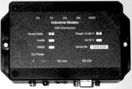
LED
- TR = DTR, Data Terminal Ready
- TX = Transmit Data
- CD = Carrier Detect from remote modem
- RX = Receive Data
- PWR = Power
|
|
Power connection
- looking from the connector side
- Positive is on the left power terminal
- Negative is on the right terminal
- Power will be 10 to 36 VDC or 18-72 VDC
- 110VAC use DC Wall power cube (wire with
stripe is negative)
|