|
10BaseT, 100BaseT -45
connectors |
here's also a very good write up
view
http://www.zytrax.com/tech/layer_1/cables/tech_lan.htm
This cable can be used to cascade hubs, or for connecting two Ethernet stations back-to-back without a hub. It works with 10Base-T, 100Base-TX, 100Base-T4 and 1000Base-T. Use a good enough cable, if you are confused about categories of cables then use category 5e(nhanced) and you'll be fine even at 1000Base-T.
RJ45 MALE CONNECTOR to network interface card 1.
RJ45 MALE CONNECTOR to network interface card 2.
(1000Base-T names in parentheses)
| Name | NIC1 | Color | NIC2 | Name |
|---|---|---|---|---|
| TX+ (BI_DA+) | 1 | White/Orange | 3 | RX+ (BI_DB+) |
| TX- (BI_DA-) | 2 | Orange | 6 | RX- (BI_DB-) |
| RX+ (BI_DB+) | 3 | White/Green | 1 | TX+ (BI_DA+) |
| - (BI_DC+) | 4 | Blue | 7 | - (BI_DD+) |
| - (BI_DC-) | 5 | White/Blue | 8 | - (BI_DD-) |
| RX- (BI_DB-) | 6 | Green | 2 | TX- (BI_DA-) |
| - (BI_DD+) | 7 | White/Brown | 4 | - (BI_DC+) |
| - (BI_DD-) | 8 | Brown | 5 | - (BI_DC-) |
That means that the white/orange cable connected to NIC 1 pin 1 should go to NIC 2 pin 3 and NIC 1 pin 2 to NIC 2 pin 6 etc.
Note 1: It's important that each pair is kept as a pair. TX+ & TX- must be in the pair, and RX+ & RX- must together in another pair. (Just as the table above shows).
Note 2: While 10Base-T and 100Base-TX only uses 2 pairs, please connect all four since 100Base-T4 and 1000Base-T needs them and save yourself some future debugging :)
Note 3: The colors originate from the numbering and name on NIC1.
RJ-45 Connectors - Patch Cables for Category 5 Wire
|
|
REMEMBER To hold the RJ45 connector with the 'clip' on the bottom. To have to the 'opening' (where you insert the cable) facing you. |
|
|
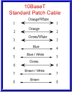
CAT5 Standard Patch Cord |
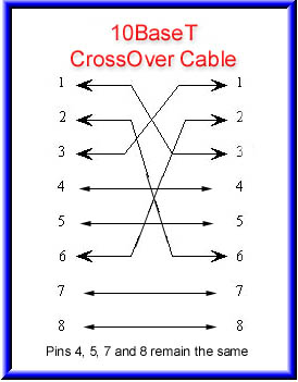
CAT5 Cross-over Cable |
|
|
|
REMEMBER For a cross-over cable make one end like the Standard Patch Cord, and one end like the Cross-over Cable. |
|
|
Straight-Through vs. Cross-Over In general, the patch cords that you use with your Ethernet connections are "straight-through", which means that pin 1 of the plug on one end is connected to pin 1 of the plug on the other end. In this particular case it is not then important to wire them as above. Pin 1 is Pin 1 etc etc. However for the sake of uniformity it may be best to wire your cables with the same colour sequence. Cross-Over cables are "crossed" end to end data cables aren't. If you have a network hub that has an uplink port on it then you do not need to make (or purchase a cross-over cable). Just switch the port on the hub to the 'uplink' mode. If your hub does not have an 'uplink' port on it then the only way to cascade another hub or attach a cable modem is to use a cross-over cable. It helps for future reference to mark or attach a tag to the cross-over cable so that you do not attempt to use it as a 'normal' patch lead at some time in the future. The only time you cross connections in 10/100BaseT is when you connect two Ethernet devices directly together without a hub. This can be two computers connected without a hub, or two hubs via standard Ethernet ports in the hubs. Then you need a "cross-over" patch cable, which crosses the transmit and receive pairs, the orange and green pairs in normal wiring. In a cross-over cable, one end is normal, and the other end has the cross-over configuration. Remember you can only network two computers together with Cat5 cable. To add extra PC's to your network you will require a hub. |
||
When working with 10Base-T wiring,
concentrators, and adapters from different vendors, it is
possible to connect everything and get no communication between
file servers and workstations. When there are several unknown
variables, it is difficult to determine which component is
broken.
Troubleshooting Techniques
The following article describes troubleshooting techniques that
can be applied to 10Base-T twisted-pair networks.
First, know whether your equipment is compliant with the 10Base-T
standard, or if it was manufactured before the standard was set
("pre-10Base-T"). This is particularly important for
concentrators (hubs or repeaters). Although the two
specifications may appear similar, small differences can cause a
network to not function properly. Following are the most common
problems encountered when working with pre-10Base-T and 10Base-T
equipment.
Common Problems with Differing Standards:
By definition, 10Base-T requires that twisted-pair wiring has an
impedance of 100 ohms. Pre-10Base-T hubs and adapters may be
configurable within an impedance range of anywhere between 75 and
150 ohms. When attempting to connect a 10Base-T adapter to a
pre-10Base-T hub, there can be an obvious impedance mismatch,
which causes the adapter to malfunction. Make sure that both the
hub and adapter are configured to the same impedance setting.
Note: Most 10Base-T adapters are designed so that they are
compatible with both pre-10Base-T and 10Base-T hubs. The
impedance range is jumper selectable on the adapter.
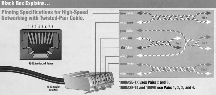
Network specialists also have many problems making 10Base-T
compliant cables. To connect a file server or netstation to a
hub, the correct 10Base-T cable must be used. An RJ-45 connector
is used at both ends of the twisted-pair cable, which consists of
four wires (two pairs). Following are the pin-outs for the cable:
+----------------+ +----------------+
| Pin 1 TD+ |-------------------| TD+ Pin 1 ---|
| Pin 2 TD- |-------------------| TD- Pin 2 ---|
| Pin 3 RD+ |-------------------| RD+ Pin 3 ---|
| Pin 4 | | Pin 4 ---|
| Pin 5 | | Pin 5 ---|
| Pin 6 RD- |-------------------| RD- Pin 6 ---|
| Pin 7 | | Pin 7 ---|
| Pin 8 | | Pin 8 ---|
+----------------+ +----------------+
RJ-45 RJ-45
A straight through cable is used to go from the adapter to the
hub. The hub performs an internal crossover so that the signal
can go from TD+ to RD+ and TD- to RD-. When looking at an RJ-45
connector from the front (that is, the opposite side from where
the wires enter the connector), pin 1 is identified on the right
hand side when the metal contacts are facing up.
Make sure that the TD+ and TD- wires are twisted together, and
that the RD+ and RD- wires are twisted together. Using wires from
opposing pairs can cause signals to be lost in the imbalance thus
created.
Troubleshooting Hubs:
When there is doubt whether a hub is performing correctly or if
the impedance settings are in question, a crossover cable can
help the specialist isolate the troublesome component. If a file
server and a net-station can be connected back to back, the
specialist can at least know that the adapters and network
operating system are properly configured. To make a crossover
cable, simply connect TD+ to RD+ and TD- to RD-. The cable
performs the crossover which is usually performed by the hub.
Following are the pin-outs for the crossover cable:
TD+ Pin 1 -------------------- Pin 3 RD+
TD- Pin 2 -------------------- Pin 6 RD-
RD+ Pin 3 -------------------- Pin 1 TD+
RD- Pin 6 -------------------- Pin 2 TD-
If the file server and net-station function together as a small
network, then either the existing cabling or the hub is the
culprit.
Note: There should only be one crossover, and it should be
performed by the hub. If a section of installed cable is
configured as a crossover cable, it cancels the hub's crossover
and creates a straight through connection.
Many adapter manufacturers (including 3Com) design an LED into
the adapter which tells the network specialist whether or not the
cabling has been wired properly. If there is a proper crossover,
then the LED lights up. If there is a straight through
connection, the LED is dark. A blinking LED indicates that there
is a polarity mismatch (that is, TD+ to RD- instead of TD+ to
RD+). The wiring is close and the adapter may or may not
function; if it functions at all, it will function poorly.
When working with 10Base-T wiring, concentrators, and adapters
from different vendors, it is possible to connect everything and
get no communication between file servers and workstations. When
there are several unknown variables, it is difficult to determine
which component is broken. The following article describes
troubleshooting techniques that can be applied to 10Base-T
twisted-pair networks.
First, know whether your equipment is compliant with the 10Base-T
standard, or if it was manufactured before the standard was set
("pre-10Base-T"). This is particularly important for
concentrators (hubs or repeaters). Although the two
specifications may appear similar, small differences can cause a
network to not function properly. Following are the most common
problems encountered when working with pre-10Base-T and 10Base-T
equipment.
Common Problems with Differing Standards:
By definition, 10Base-T requires that twisted-pair wiring has an
impedance of 100 ohms. Pre-10Base-T hubs and adapters may be
configurable within an impedance range of anywhere between 75 and
150 ohms. When attempting to connect a 10Base-T adapter to a
pre-10Base-T hub, there can be an obvious impedance mismatch,
which causes the adapter to malfunction. Make sure that both the
hub and adapter are configured to the same impedance setting.
Note: Most of 3Com's 10Base-T adapters are designed so that they
are compatible with both pre-10Base-T and 10Base-T hubs. The
impedance range is jumper selectable on the adapter.
Network specialists also have many problems making 10Base-T
compliant cables. To connect a file server or netstation to a
hub, the correct 10Base-T cable must be used. An RJ-45 connector
is used at both ends of the twisted-pair cable, which consists of
four wires (two pairs). Following are the pin-outs for the cable:
+----------------+ +----------------+
| Pin 1 TD+ |-------------------| TD+ Pin 1 ---|
| Pin 2 TD- |-------------------| TD- Pin 2 ---|
| Pin 3 RD+ |-------------------| RD+ Pin 3 ---|
| Pin 4 | | Pin 4 ---|
| Pin 5 | | Pin 5 ---|
| Pin 6 RD- |-------------------| RD- Pin 6 ---|
| Pin 7 | | Pin 7 ---|
| Pin 8 | | Pin 8 ---|
+----------------+ +----------------+
RJ-45 RJ-45
A straight through cable is used to go from the adapter to the
hub. The hub performs an internal crossover so that the signal
can go from TD+ to RD+ and TD- to RD-. When looking at an RJ-45
connector from the front (that is, the opposite side from where
the wires enter the connector), pin 1 is identified on the right
hand side when the metal contacts are facing up.
Make sure that the TD+ and TD- wires are twisted together, and
that the RD+ and RD- wires are twisted together. Using wires from
opposing pairs can cause signals to be lost in the imbalance thus
created.
Troubleshooting Hubs:
When there is doubt whether a hub is performing correctly or if
the impedance settings are in question, a crossover cable can
help the specialist isolate the troublesome component. If a file
server and a netstation can be connected back to back, the
specialist can at least know that the adapters and network
operating system are properly configured. To make a crossover
cable, simply connect TD+ to RD+ and TD- to RD-. The cable
performs the crossover which is usually performed by the hub.
Following are the pinouts for the crossover cable:
TD+ Pin 1 -------------------- Pin 3 RD+
TD- Pin 2 -------------------- Pin 6 RD-
RD+ Pin 3 -------------------- Pin 1 TD+
RD- Pin 6 -------------------- Pin 2 TD-
If the file server and net-station function together as a small
network, then either the existing cabling or the hub is the
culprit.
Note: There should only be one crossover, and it should be
performed by the hub. If a section of installed cable is
configured as a crossover cable, it cancels the hub's crossover
and creates a straight through connection.
Many adapter manufacturers (including 3Com) design an LED into
the adapter which tells the network specialist whether or not the
cabling has been wired properly. If there is a proper crossover,
then the LED lights up. If there is a straight through
connection, the LED is dark. A blinking LED indicates that there
is a polarity mismatch (that is, TD+ to RD- instead of TD+ to
RD+). The wiring is close and the adapter may or may not
function; if it functions at all, it will function poorly.
ARC Electronics
301-924-7400 EXT 25
... Home Page
E-Mail us at - arc@arcelect.com